Reading the Value of a Rotary Encoder Arduino
A rotary encoder is a type of position sensor that converts the athwart position (rotation) of a knob into an output indicate that is used to decide what direction the knob is being rotated.
Due to their robustness and fine digital command; they are used in many applications including robotics, CNC machines and printers.
There are two types of rotary encoder – absolute and incremental. The absolute encoder gives us the exact position of the knob in degrees while the incremental encoder reports how many increments the shaft has moved.
The rotary encoder used in this tutorial is of an incremental blazon.
Rotary Encoders Vs Potentiometers
Rotary Encoders are the modern digital equivalent of the potentiometer and are more versatile than a potentiometer.
They can fully rotate without end stops while a potentiometer tin can rotate only nearly iii/4 of the circle.
Potentiometers are best in situations where you lot need to know the exact position of the knob. However, rotary encoders are all-time in situations where yous need to know the change in position instead of the exact position.
How Rotary Encoders Work
Inside the encoder is a slotted disk connected to the common basis pin C, and two contact pins A and B, as illustrated below.
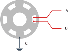
When y'all plough the knob, A and B come in contact with the common ground pivot C, in a particular lodge co-ordinate to the direction in which yous are turning the knob.
When they come in contact with common ground they produce signals. These signals are shifted 90° out of stage with each other equally one pivot comes in contact before the other pin. This is called quadrature encoding.

When you lot plow the knob clockwise, the A pin connects beginning, followed by the B pin. When yous plow the knob counterclockwise, the B pin connects offset, followed by the A pivot.
By tracking when each pin connects to and disconnects from the ground, we tin utilise these signal changes to determine in which direction the knob is being rotated. Y'all tin practice this by but observing the country of B when A changes land.
When the A changes land:
Rotary Encoder Pinout
The pinouts of the rotary encoder are every bit follows:
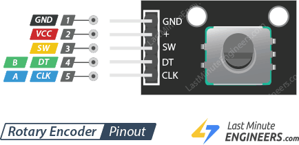
GND is the Basis connexion.
VCC is the positive supply voltage, usually 3.iii or v Volts.
SW is the active depression push button switch output. When the knob is pushed, the voltage goes Low.
DT (Output B) is the aforementioned as the CLK output, but it lags the CLK past a 90° phase shift. This output can be used to decide the direction of rotation.
CLK (Output A) is the master output pulse for determining the amount of rotation. Each fourth dimension the knob is rotated past one detent (click) in either management, the 'CLK' output goes through one cycle of going Loftier and then Depression.
Wiring – Connecting Rotary Encoder to Arduino
At present that we know everything about the rotary encoder information technology is fourth dimension to put it to use!
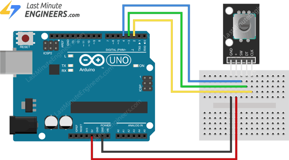
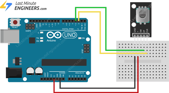
Let'southward connect Rotary Encoder to Arduino. Connections are fairly simple. Kickoff by connecting +V pin on the module to 5V on the Arduino and GND pivot to ground.
Now connect the CLK and DT pins to digital pivot#2 and #3 respectively. Finally, connect the SW pivot to a digital pin #iv.
The post-obit analogy shows the wiring.
Arduino Lawmaking – Reading Rotary Encoders
Now that you accept your encoder hooked up you'll need a sketch to brand information technology all work.
The following sketch detects when the encoder is being rotated, determines which direction information technology is existence rotated and whether or not the push button is existence pushed.
Try the sketch out; and and then nosotros volition dissect information technology in some detail.
// Rotary Encoder Inputs #define CLK 2 #define DT three #ascertain SW 4 int counter = 0; int currentStateCLK; int lastStateCLK; Cord currentDir =""; unsigned long lastButtonPress = 0; void setup() { // Ready encoder pins equally inputs pinMode(CLK,INPUT); pinMode(DT,INPUT); pinMode(SW, INPUT_PULLUP); // Setup Serial Monitor Serial.begin(9600); // Read the initial state of CLK lastStateCLK = digitalRead(CLK); } void loop() { // Read the current state of CLK currentStateCLK = digitalRead(CLK); // If last and current state of CLK are different, then pulse occurred // React to only 1 land change to avoid double count if (currentStateCLK != lastStateCLK && currentStateCLK == 1){ // If the DT country is different than the CLK state then // the encoder is rotating CCW so decrement if (digitalRead(DT) != currentStateCLK) { counter --; currentDir ="CCW"; } else { // Encoder is rotating CW so increment counter ++; currentDir ="CW"; } Serial.impress("Management: "); Serial.impress(currentDir); Series.print(" | Counter: "); Serial.println(counter); } // Think last CLK state lastStateCLK = currentStateCLK; // Read the push button state int btnState = digitalRead(SW); //If we detect LOW signal, button is pressed if (btnState == LOW) { //if 50ms accept passed since last Depression pulse, it means that the //button has been pressed, released and pressed again if (millis() - lastButtonPress > 50) { Serial.println("Button pressed!"); } // Remember concluding button press event lastButtonPress = millis(); } // Put in a slight delay to help debounce the reading filibuster(1); } If everything is fine, y'all should encounter beneath output on serial monitor.
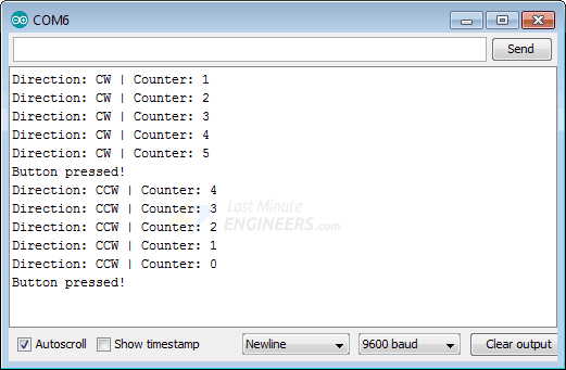
If the rotation beingness reported is the opposite of what you expect, endeavor swapping the CLK and DT lines.
Code Caption:
The sketch begins with the declaration of the Arduino pins to which the encoder's CLK, DT and SW pins are connected.
#define CLK 2 #define DT 3 #define SW 4 Next, a few integers are defined. The counter variable represents the count that will exist modified each time that the knob is rotated one detent (click).
The currentStateCLK and lastStateCLK variables agree the land of the CLK output and are used for determining the corporeality of rotation.
A string called currentDir will exist used when printing the current direction of rotation on the serial monitor.
The lastButtonPress variable is used to debounce a switch.
int counter = 0; int currentStateCLK; int lastStateCLK; String currentDir =""; unsigned long lastButtonPress = 0; Now in the Setup section, we first define the connections to the encoder every bit inputs, then we enable the input pullup resistor on SW pin. Nosotros also setup the serial monitor.
At the cease we read the current value of the CLK pin and store it in the lastStateCLK variable.
pinMode(CLK,INPUT); pinMode(DT,INPUT); pinMode(SW, INPUT_PULLUP); Serial.begin(9600); lastStateCLK = digitalRead(CLK); In the loop section, nosotros bank check the CLK state over again and compare it to the lastStateCLK value. If they are different then it means that the knob has turned and a pulse has occurred. We besides check if the value of currentStateCLK is one in order to react to only i state change to avoid double count.
currentStateCLK = digitalRead(CLK); if (currentStateCLK != lastStateCLK && currentStateCLK == 1){ Within the if statement we determine the management of rotation. To do this we simply read the DT pivot on the encoder module and compare it to the current state of the CLK pin.
If they are unlike, it means that the knob is rotated counterclockwise. We then decrement the counter and set currentDir to "CCW".
If the ii values are the same, it ways that the knob is rotated clockwise. We then increment the counter and fix currentDir to "CW".
if (digitalRead(DT) != currentStateCLK) { counter --; currentDir ="CCW"; } else { counter ++; currentDir ="CW"; } We and so impress our results on the serial monitor.
Serial.impress("Management: "); Series.print(currentDir); Series.print(" | Counter: "); Serial.println(counter); Outside the if statement nosotros update lastStateCLK with the current state of CLK.
lastStateCLK = currentStateCLK; Next comes the logic to read and debounce the push push switch. We kickoff read the current button state, if it'southward Depression, we expect for 50ms to debounce the button button.
If the button stays Depression for more 50ms, we print "Button pressed!" message on the series monitor.
int btnState = digitalRead(SW); if (btnState == Depression) { if (millis() - lastButtonPress > fifty) { Serial.println("Push button pressed!"); } lastButtonPress = millis(); } So we do it all over once more.
Arduino Code – Using Interrupts
In gild for rotary encoder to work, nosotros demand to continuously monitor changes in DT and CLK signals.
To make up one's mind when such changes occur, we tin can continuously poll them (like we did in our previous sketch). However, this is not the all-time solution for beneath reasons.
- We have to busily perform checking to run across whether a value has changed. At that place will be a waste material of cycles if indicate level does non change.
- In that location will exist latency from the fourth dimension the upshot happens to the time when we cheque. If nosotros need to react immediately, nosotros will be delayed by this latency.
- It is possible to completely miss a indicate change if the duration of the change is brusk.
A solution widely adopted is the use of an interrupt.
Wiring
Equally most Arduinos (including Arduino UNO) accept but two external interrupts, nosotros can only monitor changes in the DT and CLK signals. That'southward why nosotros removed the connection of the SW pin from the previous wiring diagram.
So at present the wiring looks similar this:
Some boards (similar the Arduino Mega 2560) accept more external interrupts. If yous have one of them, you lot tin can go along the connectedness for SW pin and extend below sketch to include lawmaking for the button.
Arduino Code
Here'southward the sketch that demonstrates the apply of the interrupts while reading a rotary encoder.
// Rotary Encoder Inputs #ascertain CLK two #define DT three int counter = 0; int currentStateCLK; int lastStateCLK; String currentDir =""; void setup() { // Set up encoder pins every bit inputs pinMode(CLK,INPUT); pinMode(DT,INPUT); // Setup Serial Monitor Series.begin(9600); // Read the initial country of CLK lastStateCLK = digitalRead(CLK); // Call updateEncoder() when whatsoever loftier/low changed seen // on interrupt 0 (pin 2), or interrupt i (pin iii) attachInterrupt(0, updateEncoder, CHANGE); attachInterrupt(1, updateEncoder, CHANGE); } void loop() { //Exercise some useful stuff here } void updateEncoder(){ // Read the current state of CLK currentStateCLK = digitalRead(CLK); // If terminal and electric current country of CLK are different, so pulse occurred // React to only one country alter to avoid double count if (currentStateCLK != lastStateCLK && currentStateCLK == ane){ // If the DT state is different than the CLK state then // the encoder is rotating CCW then decrement if (digitalRead(DT) != currentStateCLK) { counter --; currentDir ="CCW"; } else { // Encoder is rotating CW so increment counter ++; currentDir ="CW"; } Series.print("Direction: "); Serial.print(currentDir); Serial.print(" | Counter: "); Serial.println(counter); } // Call back last CLK land lastStateCLK = currentStateCLK; } Notice that the principal loop of this plan is kept empty so Arduino will be decorated doing cipher.
Meanwhile, this program watches digital pin ii (corresponds to interrupt 0) and digital pivot 3 (corresponds to interrupt 1) for a modify in value. In other words, it looks for a voltage change going from Loftier to Depression or Low to Loftier, which happens when yous plow the knob.
When this happens the office updateEncoder (often called the interrupt service routine or just ISR) is called. The code inside this function is executed and so the program returns dorsum to whatever information technology was doing earlier.
Below two lines are responsible for all this. The function attachInterrupt() tells the Arduino which pin to monitor, which ISR to execute if the interrupt is triggered and what blazon of trigger to wait for.
attachInterrupt(0, updateEncoder, Modify); attachInterrupt(one, updateEncoder, Alter); Command Servo Motor with Rotary Encoder
For our next project nosotros will utilize a rotary encoder to control the position of a servo motor.
This project can be very useful in many situations, for example, when you want to operate a robot arm, as it would let you precisely position the arm and its grip.
In case you are not familiar with servo motor, consider reading (at least skimming) below tutorial.
SUGGESTED READING

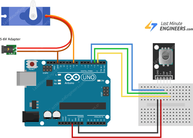
Wiring
Equally the wiring diagram shows you'll need a servo motor. Connect the Scarlet wire of the servo motor to the external 5V supply, the Black/Brown wire to basis and the Orange/Yellow wire to the PWM enabled pivot 9.
Of course you can employ the Arduino 5V output merely go on in mind that the servo tin induce electrical noise onto the 5V line that the Arduino uses, which may not what yous want.
Therefore it is recommended that you use an external power supply.
Arduino Lawmaking
Here's the sketch to precisely control the servo motor with the rotary encoder. Each time the knob is rotated one detent (click), the position of the servo arm will be changed by one caste.
// Include the Servo Library #include <Servo.h> // Rotary Encoder Inputs #define CLK 2 #define DT 3 Servo servo; int counter = 0; int currentStateCLK; int lastStateCLK; void setup() { // Set encoder pins equally inputs pinMode(CLK,INPUT); pinMode(DT,INPUT); // Setup Serial Monitor Serial.brainstorm(9600); // Attach servo on pivot 9 to the servo object servo.attach(9); servo.write(counter); // Read the initial country of CLK lastStateCLK = digitalRead(CLK); } void loop() { // Read the current land of CLK currentStateCLK = digitalRead(CLK); // If terminal and electric current state of CLK are different, then pulse occurred // React to only 1 land alter to avoid double count if (currentStateCLK != lastStateCLK && currentStateCLK == 1){ // If the DT land is different than the CLK country and so // the encoder is rotating CCW so decrement if (digitalRead(DT) != currentStateCLK) { counter --; if (counter<0) counter=0; } else { // Encoder is rotating CW and so increment counter ++; if (counter>179) counter=179; } // Movement the servo servo.write(counter); Series.impress("Position: "); Series.println(counter); } // Remember last CLK state lastStateCLK = currentStateCLK; } If you compare this sketch with our first ane you'll detect many similarities, except few things.
At the offset nosotros include the born Arduino Servo library and create a servo object to correspond our servo motor.
#include <Servo.h> Servo servo; In the Setup, we adhere the servo object to pin 9 (to which the control pin of the servo motor is connected).
In the loop, we limit the counter to have a range 0 to 179, because a servo motor but accepts a value betwixt this range.
if (digitalRead(DT) != currentStateCLK) { counter --; if (counter<0) counter=0; } else { counter ++; if (counter>179) counter=179; } Finally the counter value is used to position the servo motor.
Source: https://lastminuteengineers.com/rotary-encoder-arduino-tutorial/